Time Now

Showing posts with label Woekshop Technology. Show all posts

May 30, 2016

Riveting

Riveting


Riveting is a popular method of fastening and joining because of its simplicity, dependability and low cost.
Dissimilar metals and assemblies having a number of parts with non-uniform thickness can readily be fastened.
These joints are made in location where they either do not increase weight of the work at all
(over the weight of an integral work) or increase it negligibly. Structures in which riveted joints are used
may be grouped as: (a) where strength and rigidity are chief requirements, eg, coal bunkers, low pressure
liquid containers, ship hulls; (b) where strength, rigidity, as well as security against leakage should be
considered, eg, boiler drains, pressure vessels, high pressure liquid containers and gas tanks; and
(c) where the joint must resist given outside loads and have sufficient rigidity, eg, bridges, buildings, cranes,
and machine frames. Compared with screwed or bolted joints, riveting requires no additional work or
supplementary parts, such as, lock washers, and supplementary nuts. Compared with welded joints,
riveting makes possible consistently uniform results without resort to X-ray or other methods of inspection.
There are several types of rivets, and some may be solid or hollow; blind rivets are inserted from one side only.
Installing a rivet basically consists of placing the rivet in the hole and deforming the end of its shank by upsetting.
The operation may be performed by hands or by mechanical means, including the use of robots. Riveting may be
done either in room temperature or hot, using special tools, or by using explosives in the cavity of the rivet.

A riveted joint may fail during its service life by tearing, shearing or crushing. On a structure/machine element
a failure of a joint is reported as a failure symptom or mode. This means how the failure is observed. The
causes or cause events that singly, or in combination, may lead to these failure modes, or a general failure
mode, include design related, process related, operation/use related and maintenance related cause events.
The design related cause events include problem of strength analysis, improper selection of the type of joint,
improper material selection, improper size of rivets (shank diameter and length), improper size of rivet holes/
clearance, improper layout of rivet holes and improper size of cover plates/straps. The process related cause
events are improper riveting process, improper riveting environment and defective material (rivet and cover plates);
while operation related cause event is improper loading; and maintenance related cause events include problems of
riveting technicians and improper maintenance of material (including riveting equipment).

Upsetting Process

Upsetting Process: An Overview


Upset Forging or Upsetting is defined as 'free forming', by which a billet or a portion of a workpiece is reduced in height between usually plane, parallel plates [ASM Handbook 1988]. Upsetting is a basic deformation process which can be varied in many ways. Upsetting of metals is a deformation process in which a (usually round) billet is compressed between two dies in a press or a hammer. This operation reduces the height of a part while increasing its diameter. The process is mostly used as an intermediate step in multiple step forging operations. The billet may be cold, warm or hot forged. A large segment of industry primarily depends on the upsetting process for producing parts ranging in complexity from simple bolts, screws, nuts, rivets or flanged shafts to wrench sockets that require simultaneous upsetting and piercing. Hot upsetting is also occasionally used as a finishing operation following hammer or press forging, such as in making crankshafts. A sketch of the upsetting process is shown in the below figure.

Scrap
Figure 1: Upsetting process


In upsetting a rigid tool is pushed onto a block of material (billet). The material is free to move at the right hand side. Successful upsetting mainly depends on two process limitations:
1.Upset strain, : that affects the forming limit or forgeability of the workpiece material

          h0
ε = ln  —
          h1

2. Upset Ratio (Ru): that affects the buckling of the workpiece

          h0
Ru  =      
          d0


Figure 2: Upset Forging of a Cylinder


Figure 3: Metal flow in non-steady state upset forging processes

In upsetting a ratio of Ru≤2.3 can be achieved in one hit if the deformation occurs over a portion of the workpiece. Larger values require several deformation stages. In upsetting the parameters that are significant are dimensions of the workpiece, its strength, its formability, the required upset ratio, the desired accuracy and the surface quality. When forming in several stages, the design of the heading preforms affects the fiber structure of the final shape. Heading preforms are to be shaped such that the workpiece is guided correctly to avoid buckling and folding. In metal forming, the flow of metal is caused by the pressure transmitted from the dies to the deforming workpiece. Therefore, the frictional conditions at the die/workpiece interface greatly influence metal flow, formation of surface and internal defects, stresses acting on the dies, and load and energy requirements
In metal forming, the flow of metal is caused by the pressure transmitted from the dies to the deforming workpiece. Therefore, the frictional conditions at the die/workpiece interface greatly influence metal flow, formation of surface and internal defects, stresses acting on the dies, and load and energy requirements. Figure above illustrates this phenomenon as it applies to the upsetting of a cylindrical workpiece. The figure(a) shows, under frictionless conditions, the workpiece deforms uniformly and the resulting normal stress is constant across the diameter. However, figure (b) shows that under actual conditions, where some level of frictional stress is present, the deformation of the workpiece is not uniform (i.e. barreling). As a result, the normal stress increases from the outer diameter to the center of the workpiece and the total upsetting force is greater than for the frictionless conditions.

Piston

Pistons are vital component of reciprocating engines, reciprocating pumps, gas compressors and pneumatic cylinders etc. It is the reciprocating component which moves inside the cylinder and converts the reciprocating motion into rotary motion or vice versa.

Figure 4: Piston

Forged Piston Vs Casted Piston: The majority of original equipment and aftermarket pistons are manufactured through casting. The technical description is 'gravity die casting'. However for the sake of simplicity, a cast piston is manufactured by pouring molten aluminium /silicon alloy into a mold. Forged pistons differ fundamentally in manufacturing and inherent character. As opposed to casting, the forging process basically takes a lump of billet alloy and stamps the shape of the piston from a die.
Casting and forging results in two different types of piston. A die for forged piston must be designed so it can easily be removed and, as a result, the forged blank (or unfinished piston) has a relative simple shape. Casting can achieve a more complex blank and, therefore, facilitate lightweight construction. Also, due to relative manufacturing procedures, forged pistons tend to be more expensive than cast items. A cast pistons is more likely to shatter and damage the engine, as a whole, more than a forged piston where as a big advantage with forged pistons is they generally result in a more ductile material, with the effect being the piston can take a higher level of detonation before failing. In extremely high rpm/high horsepower applications, the great strength of the forged piston can add reliability.

Manufacturing Forged Piston: During Manufacturing of Piston the billet of Aluminium alloy is taken and hot forging operation is performed over it. The billet is preheated to a temperature of about 427 C before placing it onto the lower die and performing forging operation over it.. This leads to the upsetting operation taking place in the billet. The change in microstructure tends to increase the strength of piston. Dies used for the process consists of impression of the piston on lower die as well as the upper die as shown in the following figures:

          
Figure 5: Lower Die               Figure 6: Upper Die

The manufacturing process used in the process is shown in the following figure:


Figure 7: Manufacturing process

Alloy Whee: Alloy wheels are automobile (car, motorcycle and truck) wheels which are made from an alloy of aluminum or magnesium. They are typically lighter for the same strength and provide better heat conduction and improved cosmetic appearance. There are quality standards to govern the production of wheels. A wheel is comprised of a hub, spokes and rim. Sometimes these components will be one piece, sometimes two or three. The hub is the centre portion of the wheel and is what attaches the wheel to the suspension. The spokes radiate out from the hub and attach to the rim. Most alloy wheels are manufactured using casting, but some are forged. Forged wheels are usually lighter, stronger, but much more expensive than cast wheels. There are basically three processes when it comes to manufacturing alloy wheel which are one piece in construction: cast alloy, forged alloy wheels, and billet alloy wheels. Each one of these will produce a highest quality alloy wheels however there are some distinct difference in the strength of the finished product worth nothing.

A CAST ALLOY WHEEL - is a manufacturing process whereby molten aluminium is pored into an alloy wheel mould and once it is cooled, the result is a wheel. There are three types of cast wheel production: Gravity fed, low- pressure fed, spun-rim.

A FORGED ALLOY WHEEL - is a manufacturing process in which intense heat and pressure is used to force a chunk of aluminium (often called a slug or stock) into the alloy wheel shape desired. This process will create an alloy wheel which is up to 300% stronger than a cast alloy wheel and is lighter as well.

A BILLET ALLOY WHEEL - is a manufacturing process here by a chunk of aluminium is machined into the alloy wheel design. This involves a very expensive machine called CNC (computer numeric control) which reads specific instructions then drives the machine tool to complete the task.
Magnesium alloy wheels, or "mag wheels", are sometimes used on racing cars, in place of heavier steel or aluminium wheels, for better performance. Magnesium wheels can be produced through various methods.

FORGING: Forging can be done by a one or multi-step process forging from various magnesium alloys, most commonly AZ80, ZK60 (MA14 in Russia). Wheels produced by this method are usually of higher toughness and ductility than aluminium wheels, although the costs are much higher.

HIGH PRESSURE DIE CASTING (HPDC): This process uses a die arranged in a large machine that has high closing force to clamp the die closed. The molten magnesium is poured into a filler tube called a shot sleeve. A piston pushes the metal into the die with high speed and pressure, the magnesium solidifies and the die is opened and the wheel is released. Wheels produced by this method can offer reductions in price and improvements in corrosion resistance but they are less ductile and of lower strength due to the nature of HPDC.

LOW PRESSURE CASTING (LPDC): This process usually employs a steel die; it is arranged above the crucible filled with molten magnesium. Most commonly the crucible is sealed against the die and pressurized air/cover gas mix is used to force the molten metal up a straw like filler tube into the die. When processed using best practice methods LPDC wheels can offer improvements in ductility over HPDC magnesium wheels and any cast aluminium wheels, they remain less ductile than forged magnesium.

GRAVITY CASTING (PERMANENT MOLD AND SAND CASTING): Gravity cast magnesium wheels have been in production since the early 1920's. This method offers wheels with good ductility, and relative properties above what can be made with aluminium casting. Tooling costs for gravity cast wheels are among the cheapest of any process. This has allowed small batch production, flexibility in design and short development time.

Swaging

Swaging


Swaging is a process that is used to reduce or increase the diameter of tubes. A swagged piece created by placing the tube inside a die that applies compressive force by hammering radially.
The term swage can apply to the process of swaging (verb), or to a die or tool used for swaging (noun).

Manufacturing Processes: As a general manufacturing process swaging may be broken up into two categories. The first category of swaging involves the workpiece being forced through a confining die to reduce its diameter, similar to the process of drawing wire. This may also be referred to as "tube swaging." The second category involves two or more dies used to hammer a round workpiece into a smaller diameter. This process is usually called "rotary swaging" or "radial forging". Tubes may be tagged (reduced in diameter to enable the tube to be initially fed through the die to then be pulled from the other side) using a rotary swagger, which allows them to be drawn on a draw bench. Swaging is normally the method of choice for precious metals since there is no loss of material in the process.
Swaging can be further expanded by placing a mandrel inside the tube and applying radial compressive forces on the outer diameter. Thus, through the swage process, the inner tube diameter can be a different shape, for example a hexagon, and the outer is still circular.

Rotary Image Ajay Kant Upadhyay
Junoon`s Wiki

Tube Swaging

Rotary swaging: Rotary swaging process is usually a cold working process, used to reduce the diameter, produce a taper, or add point to a round workpiece. It can also impart internal shapes in hollow workpieces through the use of a mandrel (the shape must have a constant cross-section). Swaging a bearing into a housing means flaring its groove's lips onto the chamber of the housing. A swaging machine works by using two or four split dies which separate and close up to 2000 times a minute. This action is achieved by mounting the dies into the machine's spindle which is rotated by a motor. The spindle is mounted inside a cage containing rollers (looks like a roller bearing). The rollers are larger than the cage so as the spindle spins the dies are pushed out to ride on the cage by centrifugal force, as the dies cross over the rollers they push the dies together because of their larger size. On a four-die machine, the number of rollers cause all dies to close at a time; if the number of rollers do not cause all pairs of dies to close at the same time then the machine is called a rotary forging machine, even though it is still a swaging process.

RotarySwaging Ajaykant Upadhyay
Junoon`s Wiki

Rotary Swaging

A variation of the rotary swagger is the creeping spindle swaging machine where both the spindle and cage revolve in opposite directions, this prevents the production of fins between the dies where the material being swagged grows up the gap between the dies. There are two basic types of rotary swaging machine, the standard (also known as a tagging machine), and the butt swaging machine. A butt swaging machine works by having sets of wedges that close the dies onto the workpiece by inserting them between the annular rollers and the dies, normally by the use of a foot pedal. A butt swaging machine can allow a workpiece to be inserted without the dies closing on it, for example a three foot workpiece can be inserted 12 inches and then the dies closed, drawn through until 12 inches remain and the dies are then released, the finished workpiece would then, for example, be four feet long but still of its initial diameter for a foot at each end.

Applications

Electronics: In Printed Circuit Boards assembly individual connector pins are sometimes pressed/swagged into place using an arbor press. Some pins have a hollow end that is pressed over by the arbor's tool to form a mushroom shaped retaining head. Typical pin diameter range from 0.017 to 0.093 inches or larger. The swaging is an alternative or supplement to soldering.

Pipes and Cables: The most common use of swaging is to attach fittings to pipes or cables (also called wire ropes); the parts loosely fit together, and a mechanical or hydraulic tool compresses and deforms the fitting, creating a permanent joint. Pipe flaring machines are another example. Flared pieces of pipe are sometimes known as "swage nipples," "pipe swages," "swaged nipples," or "reducing nipples." In furniture, legs made from metal tubing (particularly in commercial furniture) are often swaged to improve strength where they come in contact with the ground, or casters.

Saw blade teeth: In sawmills, a swage is used to flare large bandsaw or circle saw teeth, which increases the width of the cut, called the kerf. A clamp attaches a mandrel and die to the tooth and the eccentric die is rotated, swaging the tip. A much earlier version of the same operation used a hardened, shaped swage die and a hand held hammer. Saw teeth formed in this way are sometimes referred to as being "set." A finishing operation, shaping, cold works the points on the tooth sides to flats. It might be considered as a side swage. This slightly reduces the tooth width but increases the operating time between "fittings." Swaging is a major advance over filing as the operation is faster, more precise and greatly extends the working life of a saw.

Firearms and ammunition: In internal ballistics, swaging describes the process of the bullet entering the barrel and being squeezed to conform to the rifling. Most firearm bullets are made slightly larger than the inside diameter of the barrel, so that they are swaged to engage the rifling and form a tight seal upon firing. In ammunition manufacture, swaged bullets are bullets manufactured by swaging room temperature metals into a die to form it into the shape of a bullet. In contrast, swaged bullets, since they are formed at the temperature at which they will be used, can be formed in molds of the exact desired size. This means that swaged bullets are generally more precise than cast bullets. The swaging process also leads to fewer imperfections, since voids commonly found in casting would be pressed out in the swaging process. The swaging process in reference to cold flow of metals into bullets is the process not of squeezing the metals into smaller forms but rather pressing smaller thinner items to form into shorter and slightly wider shapes. Swaging is used to form unjacketed bullets, usually made of a mix of lead and some antimony to improve working properties (lead alone is usually too soft). Many reloading equipment manufacturers started by marketing both reloading and bullet swaging dies and equipment.

Forging Defects

Forging Defects


Though forging process give generally prior quality product as compared to the other manufacturing processes. There are some defects that are lightly to come a proper care is not taken in forging process design.
Forging Defects can be categorized into two broad categories:
  1. Geometrical Defects
  2. Non Geometrical Defects

Geometrical Defects: The main types of geometrical defects are

1. Laps and folds
2. Underfills
3. Overfills

There are a number of other different geometrical defects that can occur during forging. These include:
  • Piping
  • Forging shape does not match design
  • Die deflection, yielding or wear
  • Eccentricity or buckling

A) Unfilled Section: In this some section of the die cavity are not completely filled by the flowing metal. The causes of this defects are improper design of the forging die or using forging techniques.

B) Cold Shut: This appears as a small cracks at the corners of the forging. This is caused mainly by the improper design of die. Where in the corner and the fillet radii are small as a result of which metal does not flow properly into the corner and the ends up as a cold shut.

C) Laps and Folds: This is caused by the improper die design, making the laps created onto the final part which is very much undesirable as they distort the surface finish and also tend to weaken the product due to internal or external cracks.
Less-than-optimum process and preform design is the principal cause of most geometrical defects. By understanding the process issues, the forge is better able to design its processes to minimize the occurrence of such defects.
When the press or hammer dies close, the work piece will move in a path of least resistance. It is imperative that the die and pre-form design create this least resistant path so that the net result is a sound forging. On occasion, the die design may create a situation in which the path of least resistance is the one that results in a defect during forging. By examining the various types of geometrical defects, the fundamental cause can be understood and the die designer can produce a die that creates a sound, defect-free product

Non Geometrical Defects: The main type of Non geometrical defects are:

A) Flakes: These are basically internal ruptures caused by the improper cooling of the large forging. Rapid cooling causes the exterior to cool quickly causing internal fractures. This can be remedied by following proper cooling practices.

B) Scale Pits: This is seen as irregular deputations on the surface of the forging. This is primarily caused because of improper cleaning of the stock used for forging. The oxide and scale gets embedded into the finish forging surface. When the forging is cleaned by pickling, these are seen as deputations on the forging surface.

Jul 27, 2015

 Cores and Furnaces


furnaces and cores used in foundry manufacturing workshop

CORES

A core can be defined as a body of sand which is used to form a cavity of desired shape and size in a casting. Core are prepared separately in core boxes.

Types of cores:

Horizontal core: 


horizontal cores used in pattern making in foundry manufacturing workshop


It is most common and simple type of core. It is assembled in the mold with its axis horizontal. It is supported in the mold at its both ends.


Vertical core: 


vertical cores used in pattern making in foundry manufacturing workshop


It is quite similar to a horizontal core except that it is fitted in the mold with its axis vertical.


Balanced core: 


balanced cores used in pattern making in foundry manufacturing workshop


It is used to produce a blind hole along a horizontal axis in a casting. As a matter of fact it is nothing but a horizontal core, with the exception that it is supported only on one end, the other end remaining free in the mold cavity.


Hanging or cover core: 


hanging or cover cores used in pattern making in foundry manufacturing workshop


A core which hangs vertically in the mold and has no support at its bottom is known as hanging core. In such case it is obvious that the entire mold cavity will be contained in drag only.


MELTING FURNACES

A melting furnace is a very necessary equipment in foundry shop. It is used to melt the metal to be casted.

TYPES OF FURNACES

The main types of furnaces used in foundries for melting of various varieties of ferrous and non-ferrous metals and alloys are described as:

Crucible furnaces: 

These are the simplest of all the furnaces used in foundries. They are used in most of the small foundries where melting is not continuous and a large variety of metal is to be melted in small quantities. In these furnaces the entire melting of metal takes place inside a melting pot called crucible, which is made of clay and graphite. These furnaces can be classified as:

a. Coke fired furnaces: 


coke fired furnaces used in melting metal as crucible furnaces in foundry manufacturing industry

These furnaces are generally installed in a formed pit and are used for melting small quantities of ferrous metals for producing iron casting and also non-ferrous metals and alloys. They are provided with refractory lining inside and a chimney at the top. Coke is used as fuel. Broken pieces of metal are placed in the crucible. Bed coke is fired in the furnace and the crucible placed into it. Afterwards more coke is placed all around the crucible.

b. Oil and gas fired furnaces: 


oil and gas  fired furnaces used in melting metal as crucible furnaces in foundry manufacturing industry

These furnaces utilize oil or gas as a fuel. In fact a mixture of gas and air or oil and air is fed into the furnace which burns inside to produce the desired temperature. The furnace essentially consists of cylindrical steel shell, provided with refractory lining inside and proper passage for entry of the fuel mixture. The crucible is seated on a pad formed at the bottom.


Cupola furnace: 

For melting of cast iron in foundry the cupola furnace is used. It has a construction in the form of a hollow vertical cylinder made of strong mild steel plates. The kindling material, generally soft and dry piece of wood, is first placed over the sand bed followed by a small amount of coke charge known as bed charge. 

cupola furnaces used in melting metal as crucible furnaces in foundry manufacturing industry
Junoon's Wiki


The coke for this charge is put in the furnace through the charging door. The kindling material is ignited through the hole. This fire spreads slowly into the coke around the kindling material. 
Additional coke is fired until the bed charge acquires the required height. Cover plated opposite the tuyeres are opened to allow the free entry of air to aid combustion and they are left open till the entire bed charge is fully ignited. A carefully weighted proportionate amount of metal, pig iron, scrap and flux is then fired over the bed charge followed by a weighed quantity of coke. 
They are repeated in alternate layers, of course a predetermined quantity of each, until the cupola is full to the charging door. If the cupola, on account of its fixed capacity, is unable to take up the entire material to be melted at a time, the remainder is fed into it after the initial charge has been melted.


ADVANTAGES OF USING CUPOLA

1. The initial cost is comparatively lower than other types of furnaces of same capacity.
2. Operation and maintenance of the furnace does not involve too many complications.
3. Cost of operation and maintenance are comparatively lower.
4. The floor area required is hardly a fraction of that required for other furnaces of similar capacity.
5. It can be operated for a number of hours at a stretch.
6. It does not involve very complicated problems in its design which is comparatively simpler.


PRECAUTIONS IN OPERATING THE CUPOLA

1. A superior refractory lining should be used to withstand high temperature produce inside the furnace.
2. The man who fires the coke and charge should place the metal charge in the center.
3. The molten metal should be tapped out well before its level rises too high in the well.
4. The tap hole should be properly closed by means of well prepared clay bott or plug.
5. In closing the tap hole care should be taken to press the plug downwards in the hole so that the splash of the molten metal does not fall on the hands.
6. The amount of air supply should be properly controlled. An excess amount of air will result in lowering of temperature inside. 

 Planning Machine


planar machine used in machine manufacturing workshop banner


It is used to perform almost the same operations as are done on a shaper but jobs of comparatively larger size are machined on the planner. 


It is commonly used for machining large flat surfaces or machining similar jobs more in number keeping the line. The surfaces to be machined may be horizontal, vertical or inclined. Several tools can be fitted on this machine to work separately or at a time to give faster output.


CONSTRUCTION


construction and working of planar machine (bed, table, housing, columns, cross rail, tool head, controls) in machine manufacturing workshop

Bed: 

It is a very large and heavy cast iron structure which is provided with cross ribs for additional strength and stiffness. In case of large planers the bed is sometimes made in two parts which are properly machined and then bolted together to form a single length of bed. 
Leveling pads or jacks are provided under the bottom of the bed to level it during its installation. The bed itself accommodates the table driving mechanisms. V-ways and sometimes flat ways are provided on the top of bed to guide and support the reciprocating table of the planer. These bed ways are straight and parallel accurately machined and scrapped. The bed ways should be constantly lubricated.


Table: 

The table or platen is also made of cast iron with an accurately machined top. It carries a box type construction provided with strengthening ribs under it in order to make it strong enough to support the heavy work over it. At its top it has longitudinal T-slots and holes to accommodate the clamping bolt and other devices. 
Under the table chip pockets are cast integral with it for collecting and removing the chips. On its side the table carries adjustable stops to reverse its motion at the end of each stroke. A common safety device i.e. large cutting tool is bolted under the table on its both sides and stops blocks are fixed on the bed on each side. 
In case of running away of the table the tool will take a deep cut into the stop block and thus absorb the whole kinetic energy of the table, bringing it to a halt without damage to machine or workman.


Housing and columns: 

These are vertical members situated on both sides in case of double housing planer and on one side only in case of an open side planer. Inside them they carry the different mechanisms for transmission of power to the upper parts of the machine. The vertical guide ways along which the cross rail slides up and down are machined at the front of columns, where side tool heads are used, they also slide vertically along the same ways.


Cross rail: 

It is a horizontal member of heavy structure which connects the two vertical housings of the machine. It provides additional rigidity to the machine. By means of elevating screws it can be moved up and down along the guide ways. 
Clamps are provided to lock the cross rail in any desired position along the columns. In order that the cross rail is moved up or down uniformly on both ends, both the elevating screws are rotated simultaneously by horizontal shaft, mounted on the top of the machine. 
Accurately finished ways are provided at the front of the cross rails for the two vertical tool heads. Inside the rail the feed rods for vertical power feed and cross feed for the tools are provided.


Tool heads: 

The planner tool heads resemble with shape tool heads in construction as well as in operation. Four tool heads can be fitted in a planer and any or all of them can be used at a time. Two tool heads can be fitted in a vertical position on the cross rails and the other two can be fitted in horizontal position on the vertical columns. 
The tool head on the cross rail can travel horizontally along the cross rail. They can also be raised or lowered moving the cross rail up and down. The side tools can move up and down along the vertical column ways. The side tools can be fed horizontally into the job or at a desired inclination. 
Both hand and power feeds can be employed for all the tool heads. The tool head can swivel on either side from its normal position and the apron can also be set at an inclination whenever needed in the same way as in shaper head. The clapper block is also hinged in similar way as in shaper so as to avoid scratching during idle stroke.


Controls: 

Various controls for governing the action of different parts of planer are systematically provided in the easy reach of the operator. The controls may be provided on a suspended pedant easily approachable by the operator. A suspended pedant usually has the controls like start, stop, automatic cut, automatic return etc. The controls are devices for quick adjustments of vertical or horizontal tool feeds, control for rapid transverse of the tool heads individually or together. These controls sometimes increases the work efficiency. 

Feb 13, 2015

Carpentry tools


tools used in carpentry shop


1. MEASURING TOOLS

four fold box wood rule measuring tool


a. Four fold box wood rule:

It is generally 2 feet long and is folded from three places. It is marked with inch and millimetre scale. The inches are further divided into 8 and 16 parts, whereas the centimetre are sub-divided into millimetres. It is used for measuring and marking.


steel rule measuring tool

b. Steel rule:

It is made of stainless steel and is marked with scales. In this scale also there is graduation in both inches and centimetre. Inches and centimetre are further divided into smaller divisions. In this scale the conversion table between different units is also mentioned.
contraction scale measuring tool

c. Contraction scale:

It is also a rule type scale used for marking patterns. Casting allowances are added to this scale.


inch tape measuring tool


d. Inch tape:

It is made up of flexible thin steel strip. It is folded around a center pin attached with a small handle. It is graduated.


2. MARKING TOOLS

pencil as marking tools


a. Pencil:

Lead pencil is generally used for marking purposes.


scriber as marking tool


b. Scriber:

It has sharp conical edge used to mark on even hard surfaces. The front edge is hardened so as to resist wear and tear. It is made up of carbon steel. It is used for measuring and marking the points and lines on the wooden stock before processing. 


marking gauge as marking tools

c. Marking gauge:

It is used to draw parallel lines. The movable portion of the gauge is adjusted to suitable position and is tightened on the stem. The piece which slides is called as stock and a scribing pin is fixed on the stem. One face of the stock remains in contact with the job while marking, by the help of thumb screw, we can tighten the stock anywhere on the stem.


mortise gauge as marking tool

d. Mortise gauge:

It is used to draw two parallel lines. Its working is similar to marking gauge except it has two sharp edges. One fixed and second adjustable or fixed.


try square as measuring tool

e. Try square:

It is used to draw lines at right angle, parallel, or to check the trueness of planed surface, it is made up of a steel blade with a heavy base.


bevel gauge as marking tool


f. Bevel:

It consists of a wooden handle fitted with adjustable blade. The blade can be rotated by 1800 with respect to handle. It is used for marking various angles.


compass and divider as marking tool


g. Compass/ dividers:

These are used for dividing equal number of parts and for drawing arcs and circles. It consists of two legs with a spring on the top of legs. A screw is also attached at the centre of legs for adjustment.


3. CUTTING TOOLS

a. Saw

A saw is multi-tooth tool made up of thin sheet attached with a wooden handle. Its teeth are ground and sharpened to achieve smooth cutting. Different types are:


rip saw as cutting tools

1. Rip saw:
It is hand saw from 30 cm to 75 cm long containing one to one and half teeth per cm. It should not be called a hand saw but a rip saw only. Cutting of the wood is done along the grains, nearly the entire length of the saw blade is used for cutting. Cutting takes place in the forward stroke and backward stroke is ideal.


tenon saw as cutting tool
2. Tenon saw:
It derives its name from the tenon form of joint. It is a thin saw ranging from 20-40cm. long, and is supported by back of wrought iron or brass; hence it is also called back saw. It contains about 4 teeth to a cm. It is used primarily for short cuts such as for tenon’s. so, the blade is provided with a reinforcing strip or back at the top so the blade is prevented from bending during operations.


coping saw as cutting tools


3. Coping saw:
It is used for cutting quick or sharp curves either internal or external. For cutting the internal surfaces first drilling is done and then the saw blade is inserted in the hole for cutting. It consists of approximately 10 teeth per cm.


compass saw as cutting tools

4. Compass saw:
It is a short narrow saw, tapering towards the point, used for cutting sweeps and large interior curves by hand, sometimes termed as a table saw.


keyhole saw or pad saw as cutting tools


5. Keyhole saw or Pad saw:
It is used for cutting thick internal curves where it is impossible to use other saws.


cross cut saw as cutting tools


6. Cross-cut saw:
It is a saw provided with two handles, one at each end. Used for cutting heavy timber across the grains.


bow saw as cutting tools


7. Bow saw:
It consists of a wooden frame, a bar, a string, lever and two handles. It is used to produce curved surfaces with quick turns. The blade is tightened with the help of string and lever.


***SETTING OF SAW TEETH: The teeth of saw are bend in opposite direction alternatively. It is known as saw teeth setting. It is made to form a clearance between two cutting edges so that the saw may work without any restriction.


b. Chisels

firmer chiesel as cutting tools


1. Firmer chisel:
It is general purpose chisel used to finish inside grooves. It has various sizes of cutting edge depending upon the work to be done. Width varies from 5-35 mm. The cross section of the blade is rectangular in shape the wider portion of the rectangle shows the width and the smaller side the thickness.


mortise chiesel as cutting tools


2. Mortise chisel:
It is used to make mortises. This chisel is used for heavy cuts. The blade thickness varies from 5-12 mm. because of wider thickness this blade is stronger in comparison to other chisel of same size, therefore, it is capable of taking the heavy blows.


gauge chiesel as cutting tools


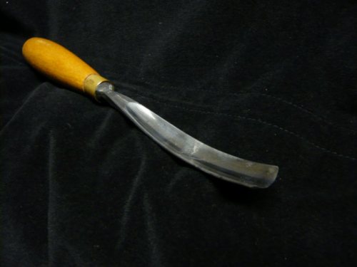
3. Gauge chisel:
It is used to finish curved holes. Gauge chisel are of two types i.e. inside and outside. 


4. PLANNING TOOLS

These tools are used for smoothening purposes, preparing proper sizes and for forming curved wooden strips. Different types of planes are:


wooden jack plane as planning tools


a. Wooden jack plane:

It s length is 20”-30” and used for general purpose. It consists of a wooden body called as stock at an angle 450 with respect to sole and material of the blade is high carbon steel. The projection of the blade from the sole is controlled by tapered wooden wedge.


iron jack plane as planning tools


b. Iron jack plane:

This plane is used for better finish. It is made of cast iron with wooden handle at the back and a wooden knob at the front, so that it can be held by both the hands during operation. This plane have a rigid and stronger body in comparison to wooden jack plane, but it is costlier.

trying plane as planning tools


c. Trying plane:

The length of this plane is 20”-30” and looks like a jack plane. It is used after surface is already planed by iron jack plane for making it true.


rebate plane as planning tools


d. Rebate plane:

This plane is used to prepare the edge of a board, the cutting edge of the blade can be adjusted for cutting rebates of different width and depth and it is used mostly for making household furniture’s.


plough plane as planning tool


e. Plough plane:

This plane is used for making groove at the same time there is also another plane called hollow plane that is used for producing the curved grooves.


spoke shave as planning tool


f. Spoke shave:

The blade of the spoke shave can be adjusted i.e. blade can be raised or lowered at the same time it can adjusted laterally also by the help of nuts. In case of smoothing a concave inside surfaces a spoke shave having round bottom is used.


rasp as planning tool


g. Rasp:

It is also known as rasp file. It is a finishing tool used to make the wood surface smooth, remove sharp edge, finishing fillets and other interior surfaces. Sharp cutting teeth are provided on its surface for this purpose. This file is used in wood work only.


5. DRILLING AD BORING TOOLS

hand drill as drilling and boring tool


a. Hand drill:

It consists of a spindle, drill chuck, crank, handle and two bevel gears. Bevel gears are fitted on the body. Drill is held in chuck and rotation to spindle is given through gears with the help of crank. The handle is pressed into the wooden piece while rotating the drill. Thus hole is formed.


ratchet brace as drilling and boring tool


b. Ratchet brace:

It consists of a crank, a head, a ratchet and a chuck for holding the drill. Any type of drill or drill bit can be held in the chuck. The head is pressed with one hand and the crank is rotated by the second hand.


gimlet drill as drilling and boring tool

c. Gimlet drill:

This drill is very simple type of drilling tool. It consists of two parts. One is gimlet and second is drill. Gimlet is made from a long twisted bar. It has a screw type starting edge. While drilling it is rotated and pressed on the wooden work piece with the help of the handle.


6. HOLDING TOOLS

work bench as holding tool


a. Work bench:

It is table which is made of sal or sheasour wood. Size of table is 6’ * 3’. Two to four carpenter’s vice are fixed at the four corners of the table. This table acts as a base for all the carpentry or wood working operations.


bench hook as holding tool


b. Bench hook:

It is a simple type of holding tool used for supporting the wood while working on it. It is used on work bench. Sawing and planning are mostly done on it. 


clamping vice as holding tool


c. Clamping vice:

It is used for sawing, joining or cutting more than one strip of wood at the same time. It’s one end is clamped to the table while the other is kept movable. Vice is made up cast steel and jaws are lined with hard wood.


C clamp as holding tool


d. C-clamp:

It is simple type of clamping device. It is generally used to paste one wood on the other or for alignment purposes.


7. STRIKING TOOLS

These are used to force the nails or chisels into the wood. Main striking tools are:
cross pean hammer as striking tool


a. Cross pean hammer:

It has a cast steel body and a wooden handle. Body has two parts face and pean. In this hammer the pean is in the form of narrow round edge ridge placed at right angle to the axis of the handle.


claw hammer as striking tool


b. Claw hammer:

It is used for striking as well as for pulling the nail from the wood. The material of the wood is case steel. One end is made striking and the second is claw face. Its weight varies from 0.25-0.75 kg.


mallet as striking tool


c. Mallet:

It is used to strike the chisels which have wooden handles. It is made up of a hard wood and is round or rectangular in shape.


8. SHARPENING TOOLS

water stone as sharpening tool


Water stone:

It is a rectangular piece of stone generally kept in a wooden base. It is used to re-sharpen the chisels, bits, plane blades and other tools. While sharpening water is sprinkled on the stone.


9. AUXILARY MATERIALS USED IN CARPENTRY

nails as auxilary materials


a. Nails:

Nails are used for fastening different wooden parts. These are made up of low carbon steel, brass or copper. These are available in the many shapes and sizes in the market. The size is taken as the overall length of the nail and wire diameters.


screws as auxilary materials


b. Screws:

Screws are generally used for fixing metallic fittings like handles, hinges etc. and joining different wooden parts. The screws give better strength to the joints then nails. These are also available in different shapes. A hole is drilled before putting the screw. Screw are made up of bright drawn wire.


bolts and nuts as auxilary materials


c. Bolts and nuts:

These are used for making heavy joints. These are specified by the length, diameter and pitch of the thread on it. Bolt is inserted in a pre-drilled hole and nut is tightened by placing a washer in it.


glues as auxilary material


d. Glues:

The pastes used for joining various wooden parts are known as glues. A permanent joint is formed with glue. Surface to surface and face to face joints can be easily made with glues.
Glues are used cold as well as hot. The commonly used glues and animal glue, resin glue, vegetable glue, milk glue, blood-albumen glue and contact cement.


paints as auxilary material

e. Paint:

It is a semi liquid past prepared by mixing a base, a vehicles and a pigment. Driers and fillers are also added in it to obtain good quality.

Functions of paint:
1. To protect the surface from moisture and corrosion.
2. To improve the appearance.

Properties of a good paint:
1. It should be dry quickly.
2. It should give a pleasing appearance after drying.
3. It should not show cracks after drying.
4. In wet condition, it should have enough flowing power.
5. It should not be affected by moisture.
6. It should not change the color due to heat or water spread on it.
7. It should have long life.
8. It should be easily available at reasonable cost.